Soldered Wheel Collars

These days you can get collars to keep wheels in place on wire undercarriages. They are quick and easy to install but they can easily fall off too. I use thread locker on the grub screws that hold the collars in place.

There is another way. Solder washers on to your undercarriage axle to hold the wheel in place.

I use a brass washer with a hole the same diameter as the undercarriage leg to make a collar that will hold a wheel in place (and won’t fall off). But, how do you stop solder and your soldering iron from damaging the wheel while soldering the washer in place? Even if you are using wheels with a metal hub there’s still a risk of accidentally touching the tyre with the soldering iron. The answer is to use a cardboard protector.

Put a cardboard protector over the wheel.

Cardboard Protector in Place

Solder the washer in place.

Washer Soldered to Undercarriage

Remove the cardboard and hey presto a soldered wheel retainer.

Finished Collar

Starting a Glow Motor – Part 1

I decided to write this after I saw a video on YouTube on how to start an RC glow engine that would, in my opinion, be better titled “How not to Start an RC Glow Engine”. The demonstrator did not know how to prime the engine and jammed the starter on to it for what seemed like forever until the poor thing finally submitted and started.

Firstly, a few terms used in this article and the following ones.
Flooded: There’s far too much fuel in the engine for it to start.
Lean: The needle setting is such that the engine is not drawing enough fuel (and oil!)
Prime: The act of drawing fuel into the engine so that it’s ready to start.
Needle Valve: The valve on the engine that controls the fuel/air mixture.
Rich: The needle setting is such that the engine is drawing more fuel than really necessary.

Both a lean or rich mixture will cause the motor to run at less than peak power but if the mixture is too lean then the engine will overheat and possibly seize. A rich mixture will cause the engine to misfire every other stroke known as “4 stroking” and will not harm the engine. For stunt flying the mixture is often deliberately set to 4 stroke.

Secondly, a few preparation steps that you can do at home.

Your propeller should be balanced to keep vibration down to a minimum. Excess vibration will shorten the life of your engine, aeroplane and I can’t imagine it would do radio gear much good either. Quite often I find, despite my best efforts, it necessary to balance my propellers several times before vibration is down to an acceptable minimum.

Once you’ve done that don’t just put the propeller onto the engine. Position it such that the propeller comes up to the engine’s compression in a comfortable position for flipping it. This is a matter of personal preference but I like the 8:10 (ten past 8) position. With electric starters, this is probably not so important.

If you’ve got a panel with an ammeter, like me, check the current required to make the glow plug filament glow orange. Most of my glow plugs are the same make so a single setting should suit. If I’m changing the model during a flying session I’ll turn the setting down before attaching it to a model so that I can bring it up to around 3 amps rather than finding out the setting is too high by blowing the plug when the lead is attached.

I’ll assume the needle setting is set more or less right. If not refer to the engine instructions if available. Otherwise generally 3 turns open from fully closed is a good place to start. I find that not much adjustment is needed between flying sessions. Once I’ve got a setting I’m happy with I’ll keep the adjustments small. You will need to adjust it now and then as the optimum setting depends on all sorts of things such as; the fuel tank and its position, propeller, altitude, ambient temperature and air pressure, humidity and fuel used. I have even found the length of lines used can affect the setting (when the model is flying). If you’ve changed any one of these then it’s likely you’ll have to adjust your needle valve setting. If like me you fly the same setup in the same place most weekends you’ll likely find that you shouldn’t need to change the setting much from week to week.

1) Prime the engine by placing a finger or thumb over the venturi and turn the engine over. Don’t do this with the glow lead connected, just in case it starts or kicks unexpectedly. The number of turns depends on the engine. Some engines like to be wet others don’t. Generally, 3-5 turns will be plenty. An inverted engine is much easier to flood so will need less priming. Remove your finger from the venturi and flip the propeller over a few times to distribute fuel in the engine. This method also works with an RC carburettor. If this method doesn’t draw fuel into the engine then it is likely there is a leak or blockage somewhere. If you’re not using a muffler you can, alternatively, also put a few drops of fuel into the exhaust port to prime it or squirt a few drops of fuel into the venturi and flip the engine over a few times.

2) Now we’re ready to attempt to start it. Attach the glow lead and hold the plane firmly with your free hand. Your helper should hold the fuselage of the plane and the outboard wing.

3) Use a finger protector; I use finger guards made by Kavan but any thick rubber pipe, such as a car radiator hose, that fits your finger should be OK. A chicken stick can also be used. Flip the propeller smartly with your protected finger using both your arm and wrist making sure that your finger moves well out of the way.

4) The engine should start after a few flips.

As you’ve probably guessed by now I don’t often use electric starters, I don’t own one. But given the way I’ve seen other people using them a suggestion, I would make, is don’t jam the starter onto the engine for long periods. If the engine doesn’t start after a few seconds then it’s not going to start at all with the current settings. Also using the starter for short periods often seems to work as well.


Fixing Tail Wheels to Profile Models

Usually, when fitting a tailwheel or skid to a profile fuselage the method shown on the plan is often to simply poke a hole in the fuselage to accept the wire and glue it in place. It never struck me as being a satisfactory way of fixing a skid particularly if you attach the skid to a self-launching device.

Typical tail fitting to a profile fuselage.

Another method I’ve seen is to drill a hole into the fuselage to accept a dowel with the wire skid running through the dowel.

The first problem I had with this method is the practicality of getting the fuselage into my drill press to drill the hole at the angle shown and to be sure I get the hole square. The second was drilling a hole in the centre of a small piece of dowel.

Some time ago I came across a better way to fit wire tailwheels or tail skids to profile models.

First, sandwich your skid between two pieces of balsa. Note the angle at the end of the wire which stops it from twisting. I use epoxy for this job. The whole job was clamped into a vice while the epoxy cures.

Once the epoxy is cured cut a slot in the profile fuselage wide enough to accept the balsa covered end of the skid with a nice snug fit.


Removing Oil from Wood

I thought I’d share a tip that was given to me a while ago regarding removing oil from wood using cornflour.

I have found the following works reasonably well.

Mix about 2 tablespoons of cornflour and acetone so that it has a creamy consistency. You may have to do this several times since acetone is very volatile.

Brush the mixture thickly on to the oil affected areas fairly quickly using small brush strokes. The acetone will evaporate almost as soon as the mixture is applied.

Leave for a day or two, remove the cornflour, and re-apply where necessary.

I have had to repeat this process many times for badly affected areas but they gradually became noticeably less oily. You’ll also find that as the wood becomes less oily the cornflour will be easier to brush off too.

Don’t bother trying to clean the brush after application. Just let the acetone evaporate and then the cornflour can be removed quite easily when the brush is dry.

Acetone may remove paint and other finishes so If you are treating a small area then you’ll need to make sure you protect the paintwork from the effects of acetone which will remove paint and dope.

I have also tried the same method with methylated spirits which is cheaper, less volatile, and gives you a bit more time to apply the mixture. It seems to work just as well although I had removed most of the oil from an airplane using the method described above, by the time I started experimenting with it. I suspect other relatively volatile solvents will work though using something oily, such as turps, would obviously defeat the purpose of this process.

Midi-Slow

Some years ago I built Dave Clarkson’s Mini Slow (plan). It was a very strong airplane. I think I crashed it around about 10 times before the fuselage and tailplane finally gave up and shattered into several pieces. Remarkably the wing is still intact so sometime I’ll get around to building another fuselage and tail-plane for it. The broken pieces also showed what a crappy job I did in gluing the wing to the fuselage. There were quite a few gaps as evidenced by the intrusion of a fair bit of paint into the join. The lesson I’ve taken away for constructing the Midi Slow is to use epoxy rather than PVA to join the fuse to the wing.

Incidentally, the nose on the Mini Slow is quite short so I intend to make the replacement 1/2 an inch longer to better accommodate a commercial tank.

In the meantime I had started building 2 Midi-Slows, the plan for which had appeared in Aeromodeller in March 2018, it’s not a large or complex plane so I thought why not build two together? I intended to give one of them to another club member who’d commented sometime before that he wished he had something as strong as the Mini Slow but unfortunately he was struck down by ill health before I finished it and has ceased flying. At least I have a spare now.

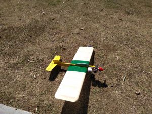
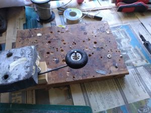
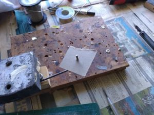
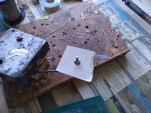
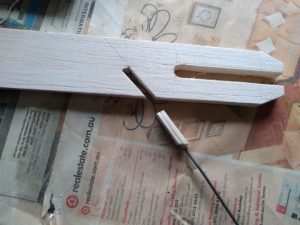
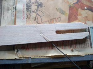
As suggested in Dave Cowburn’s Aeromodeller article I made a template cutter as I was building two. Another modification I made was to cover the ribs with Silkspan as a good lightweight way of adding strength. I found this suggestion in the article accompanying the plans of a combat model (an Ironmonger which I still haven’t finished). I also added a bellcrank stabiliser as suggested too.

I’m a digital subscriber to Aeromodeller and found that I had to do a lot of mucking about to get what I hope is an accurate print of the plan. Well, it isn’t really a plan as such but a couple of pages of diagrams and some full-size templates for some parts such as the wing ribs.

This is where I found some inconsistencies. For instance, the cut-out diagram for the parts suggests that the span of the tail-plane is 13 inches but from the plan printed on another page it is 12 inches. But as it’s not a precision stunter and I suspect it won’t make a big difference I opted for the one that was drawn on the plan which is still quite a bit bigger than the Mini Slow tailplane.

My suggestion for inexperienced scratch builders would be to get a pukka plan.

This is also the first time I tried building two supposedly identical models at the same time and despite my best efforts I found that parts that were supposed to be the same were slightly different so I ended up numbering the parts for each plane so that I wouldn’t lose track of which parts went with which plane.

Rather than use a bicycle spoke as a pushrod I used music (piano) wire. As I had used a Z bend and I was using a 2-inch Brodak nylon bellcrank which isn’t just a flat plate I found it better that the pushrod exits the wing via the top surface rather than the bottom and since the lead-out holes on the plan aren’t quite right for this bellcrank I ended up enlarging the holes in the rib nearest the bell crank. As this potentially weakened rib (E) I reinforced it a bit.

With regard to wingtip weights 3 x 2 pence pieces are suggested. According to Wikipedia, a 2 pence piece weighs 7.1 grams. As best I could estimate I used 4 large flat washers which I had bought for another plane that I estimated to be just about 6 grams each. I determined this by weighing all of them and dividing the number weighed.

I always cover the solid surfaces (tailplane, fuselage, etc.) of my planes with Silkspan. This adds strength and better seals the wood. I think it is what helped my Mini Slow last so long. This is also the first time I’ve used Koverall which is easy to apply and shrinks to a drum-tight finish. In brief, I doped down the Koverall onto the wing frame. I didn’t worry too much about getting it too tight at this stage. Once I was satisfied that the covering had been securely attached to the frame I applied a covering iron set at about 130C which I used to shrink the covering before sealing it with 50/50 Dope/Thinner mix. I also found some bubbles on solid surfaces, these were easily shrunk away using the iron. Rather than shrinking one surface at a time, I did it wing bay by wing bay (top and bottom) to reduce the likely hood of the wing warping. Despite this precaution, I noticed that on one of the planes the wing had warped. Fortunately, this was easy to remove. I just twisted the wing against the warp and heated the surface I wanted to stretch. I’m pleased with the result.

When it came to finishing I spray painted the fuselages and tailplanes and I tried a technique which I discovered in 1967-68 Aermodeller annual. Briefly, it uses gummed paper and paint. The basic idea is to paint on to the gummed paper, glued side up, to make transfers which you then carefully cut to shape, remove the paper (in water like a transfer) and place on the outline of the shape you want to make, which you’ve drawn in pencil on your airplane, painting in the remaining area without the need to paint up to the edge of the outline. I’ll be writing another article about this technique. In the meantime, you can find the original here on page 91.

To fuel proof the models I sprayed the fuse and tail with Topflite Lusterkote (unfortunately no longer available.) I’ve used Lusterkote on nearly all my models and found it to be an excellent fuel proofer. As Lusterkote is fairly expensive I decided to fuel proof the wings with Bondall marine varnish thinned with about 10 to 15% of lacquer thinners. As per usual when using varnish I found it difficult not to get runs.

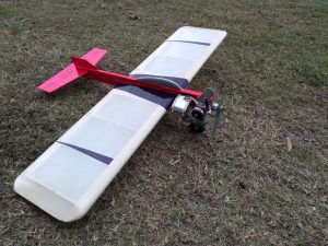
I also discovered that the pink paint (Dupicolor Hot Pink) I used to paint one of the models has very poor adhesion to Lusterkote (and it doesn’t seem to adhere too well to anything else either!) I discovered this by accident when I used some masking tape on the Lusterkote and it came away with the tape when I removed it. This is the first time I’ve had trouble with Lusterkote. I tested some varnish and it seems to adhere to the pink paint ok so I peeled off the Lusterkote, using the technique I had accidentally discovered using masking tape, and re-finished the model with varnish. To be honest it doesn’t look great but I won’t be entering it into any competition where appearance is judged.

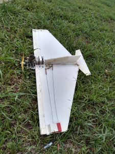
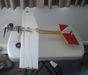
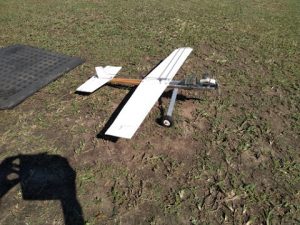
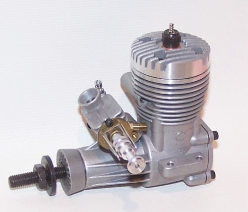
I finally finished it and flew it on 55ft lines on a calm winter day. The model is powered with an ASP 15 which is a great motor with fuel fed from a Brodak 2oz Uniflow wedge tank (part no. BH-588) which gives flights of over 6 minutes. This is an excellent combination and the motor never hesitated and I felt confident enough with it to try a lazy 8. I found it quite fast, but not too fast with excellent line tension. It was a bit twitchy, possibly because it has a huge elevator. On the second flight, I reduced the elevator throw but it didn’t seem to make much difference.

P.S. Unfortunately I crashed one of my Midi-slows not long after I finished writing this article it while trying a lazy 8 and just trying to hold model inverted a bit longer. Whilst the wing remained intact the nose broke off basically where the engine bearers join the fuselage. The position of this join is very near to the leading edge of the wing which I think made the nose quite weak at that point. I think a suitable improvement would be to either to lengthen the bearers by about 1 inch or if you constructed the fuselage as per plan using 4 1/2 inch sq strips then shorten the bearers so that they finish just about were the undercarriage is.

This is a personal preference but as I like to try to fly inverted holding my hand horizontal with my palm pointing up another useful modification would change the leadouts so that the down leadout is at the front. This (in theory) means that if you can’t keep up with the model whilst it is inverted then it should climb rather than dive.

Corflute Models

Some years go I made a Corflute combat model as detailed in Australian Control Line News issue 187 (June 2014). It’s very robust and I’ve crashed it many times, though it is now finally starting to show as the Corflute is starting to tear in places.

Combat Model
Corflute Combat Model

This design inspired me to consider how Corflute could be used to make other types of robust easy to build, easy to repair control line models.

The most obvious thing to try was a basic trainer. The Corflute trainer I designed is based on a design I found on Outerzone. It’s mostly made from Corflute and other non-traditional aeromodelling materials. It was designed to be easy to make and repair and doesn’t require traditional balsa wood model building skills. Though these skills should be acquired as this opens up access to a huge range of C/L model designs via kits and readily available plans.

Basic Trainer
Basic Trainer

I did get to try the trainer out on a novice. Whilst it withstood the inevitable errors with aplomb it failed in a way I didn’t expect. The prop-shaft of the engine I used was bent after what seemed to be just a glancing blow off the ground which didn’t look all that severe to me. Small model aircraft engines are generally pretty robust, the one on the combat model (an Enya 15) is still going strong. Before I used it in the combat model it was in another model that was crashed a few times as well.

Feel free to download the trainer building instructions from here. I’d be interested in feedback if you try to build one. I don’t intend to make another because I believe I have discovered an even simpler construction method inspired by “Tuff Baby”, details in this video.   It is similar to the combat model in some respects. I have modified the design to have more trainer like dimensions and enlarged it for a 2.5cc engine. I’ll update this post when the model and instructions are finished.

I also intend to design a stunt trainer so that basic maneuvers such as loops, bunts and inverted flying can be tried out without fear of damaging a traditional model beyond easy repair.

Here’s a photo of a model made by a fellow club member.

eBay Engine Buying Guide

I’ve bought a number of engines via eBay most of which were satisfactory but I’ve got a few duds as well. Ebay is basically buyer beware market though some sellers will accept returns.

Here are some things I think you should look for with an engine you are considering buying: It should be relatively clean and damage free i.e. no broken lugs or chipped fins. Make sure the engine has a prop nut, prop washer, prop driver, venturi, spray bar and needle valve; these are items that are relatively easy to loose and could be difficult to replace.

Here’s a picture of a C/L engine showing the items I’ve identified above.

20181004_153121.jpg

Other things to look for: Bolts with damaged heads indicates they’ve may have been over tightened as a result of the engine having been disassembled or tightened using an incorrect tool.

Sometimes modellers will modify the mounting holes to suit the plane they are installing the engine into. This is not necessarily bad but could weaken the lugs.

I have also noticed that well trusted suppliers know how to photograph their products. If the pictures are in focus, against a light plain background that differs in colour from the engine and if there are plenty of them that should be a good indications.

Here some examples. Please note this is my opinion, I’m not an expert photographer.

Good. The subject is well lit and taken there are no shadows, its clear and in focus.

s-l500


Average: Not a uniform background but in this case it doesn’t detract from the photo.

s-l16001.jpg


Poor: The subject is out of focus, its dark and the photographer’s hand obscures part of the photo and there’s clutter in the background.

s-l1600.jpg

The one thing you can’t see via eBay is the engine’s compression. Low compression will make the engine difficult if not impossible to start and if it runs it will lack power. An engine may be described as having good compression but without measuring it this is a bit subjective and you won’t really know until you get engine.

The other thing that is not easily detectable via photographs is if the needle valve is bent. This can happen in a crash.

Another thing to note is that many older engines do not come with mufflers (silencers) which may be required where you intend to fly. After market mufflers are available from various sellers on eBay and other suppliers such as Mecoa (mecoa.com).

Older glow engines (before 1980s) often need a fuel that contains about 25% castor oil. Most fuel available at hobby shops these days only has 20% synthetic oil. On the subject of synthetic oils vs castor oil you’ll find that 2 aeromodellers have at least 3 opinions between them, both types of oil have their merits and drawbacks.

If you’re buying an older engine you might be able to find a test report on Sceptre Flight which may describe the oil content of the fuel used for the test and this was presumably as specified by the engine manufacturer.

If the engine comes with a Glow Plug consider that a bonus (Glow Plugs aren’t free) but don’t dismiss and engine if it doesn’t have one.

Don’t forget to factor in postage. Many U.S. sellers seem to charge exorbitant postage, possibly a substantial portion of the cost of the item itself. I recently bought an engine where the  postage was more than half the total cost. Be wary if the seller uses the Global Shipping Program. I recently had an engine confiscated via that program

The first thing to do when you get the engine is to put a few drops of light oil such as 3-1 into the engine via the venturi and exhaust (or remove the glow plug and put a few drops in that way.) If the engine is new and hasn’t been run this is unlikely to be necessary. This is to protect it after a run as a previous owner may not have and if engine is stiff and gummed up having not being run for a while. Do this after a flying session too.

Refurbishing a Cosmic Wind

Refurbished Cosmic Wind

Quite a few months ago I bought a Cosmic Wind from a fellow club member. When I acquired this model it looked a bit tired and I was originally only intending to recover the wings as the film had numerous small holes and patches. The fuselage was a bit grubby but otherwise looked OK. In the end I recovered and re-painted the whole model. Having taken the covering off the wing I found there were a few minor repairs to be made and quite a lot of the wing and fuselage were oil soaked.

Removing the film took ages as I ended up with numerous small pieces of film stuck to the wing frame. The best way I found to remove these is to firmly press packing tape onto the bits of film and peeling it off quickly. If this technique is used be sure any sheeting is firmly fixed otherwise you may end up breaking the sheeting as I did in a couple of places.

When I looked on YouTube for film removal techniques the trick apparently is to heat the film before removal.

When it comes to removing oil I have found the following works reasonably well.

Mix corn flour and acetone so that it has creamy consistency. You may have to do this several times since acetone is very volatile.

Brush the mixture thickly on to the oil affected areas fairly quickly using small brush strokes. The acetone will evaporate almost as soon as the mixture is applied.

Leave for a day or two, remove the corn flour, and re-apply where necessary.

I had to repeat this process many times for badly affected areas but they slowly became noticeably less oily and as the wood became less oily the cornflour was easier to brush off too.

Since I was recovering a model I didn’t really care about getting acetone on the remaining paint work. If treating a small area then you’ll need to make sure you protect the paint work from the effects of acetone which will remove paint and dope.

I have also tried the same method with methylated spirits which is cheaper, less volatile and gives you a bit more time to apply the mixture. It seems to work just as well although I had removed most of the oil by the time I started experimenting with it. I suspect other relatively volatile solvents will work though using something oily, such as turps, would obviously defeat the purpose of this process.

The tail-plane was replaced as it had previously been broken at the join to the fuselage and had been repaired. It was broken again during the paint removal process and trying to make a neat repair didn’t really seem possible. I carefully cut around it ending up with a slot about 3/8 of an inch wide (approx 9mm) which I squared off and packed down to 1/8 inch to accommodate the new tailplane. I kept the original elevator, I should really have made a complete new unit as I’ve ended up with a largish gap between tailplane and elevator where I didn’t spend enough time getting the edges matched. Nevertheless the model seems to fly OK.

The wing is plastic film covered and the rest of the model is Silkspan covered on all solid surfaces for strength and sealing then filled with thinned dope mixed with Sig micro-balloons and sanded with 400 grit paper for a really smooth finish.

The covering film supplied was by Wights Model Aircraft and I was a bit worried that given the low price that it might be well… a bit mediocre. It turned out to be excellent value for money. The backing is easy to remove, it sticks well and shrinks nicely to a drum tight finish and I’m really pleased with the result. Use about 130C for tacking it down and 160-170C to shrink.

Well, I finally finished it and flew the model on 60ft lines on a windy winter day. It had no problems with the wind and it has heaps of line tension. The tank plumbing needed to be fixed since I found the engine would fade at the top of a loop and after my 2nd flight the clunk had somehow worked its way to the front of the tank causing the engine to cut at the top of a loop. I re-plumbed the tank replacing fuel tube to the clunk with something a bit stiffer. I also changed the vents to be arranged more like a conventional stunt tank.

The model is powered by a Merco 35. I don’t know its vintage but I suspect it dates back to the early 1960s, a time when engine manufacturers were predominantly manufacturing non-RC engines. The C/L venturi is cast into the crankcase with no option to change it for an R/C carbie. It also looks very similar to the Merco 35 engine drawn on a 1962 plan (Wallaby – Outerzone) and an engine test I found on Sceptre Flight – Merco 35.

An earlier version of this article is published at Wights Facebook page.